There’s a certain honesty in exploded technical drawings.
Nothing is hidden.
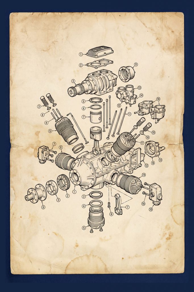
Every bolt, piston, ring, and shaft is laid bare — not for decoration, but for understanding.
This exploded diagram of an early industrial engine captures that philosophy perfectly. Rendered in the meticulous linework typical of late-19th and early-20th-century engineering drafts, the illustration breaks the machine down to its essential components, showing how power was created, transferred, and controlled long before computer modeling existed.
What you’re looking at is not just an engine — it’s problem-solving frozen in ink.
A Blueprint for the Mechanical Age
Before CAD software, before simulations and digital twins, engineers relied on drawings like this to communicate ideas with absolute precision. Each numbered component served a purpose:
- Pistons and cylinders converting combustion into motion
- Crankshafts and gears translating force into usable rotation
- Valves, housings, and fasteners designed for durability and serviceability
- Modular construction that allowed machines to be repaired, not replaced
These diagrams were instructional tools, manufacturing guides, and maintenance manuals all at once. They assumed the viewer wanted to understand the machine — not just operate it.